An underactuated hand
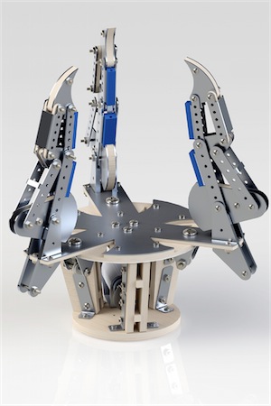
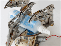
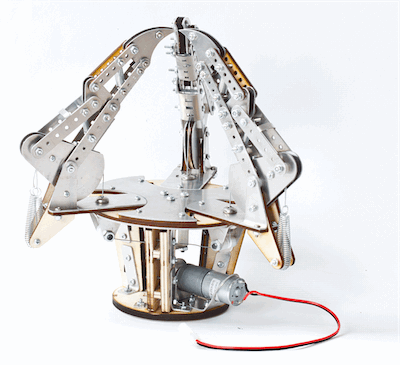
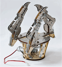
A hand is underactuated when it has more degrees of freedom than means by which it is powered. Ours has one motor. It pulls a cable at the base of each of three linkage fingers, and the fingers are shaped so that whatever they bump into obstructs part of the linkage — which makes the remaining joints curl inward around it. The hand conforms to the object instead of being told what shape the object is.
Introduction
We set out in two months to iterate through three prototypes — first in RP thermoplastic, then sheet metal and plywood, and finally a combination of the three.
The design was limited to one 12×15in birch plywood sheet (1/4in), one 12×15in birch plywood sheet (1/8in), one 12×12in sheet of sheet metal, $30.00 of RP thermoplastic, any length of steel cable, and one motor. Within those constraints (mostly), we built a hand to compete on grasping envelope, dexterity, aesthetic appeal, and the ratio of object mass to hand mass.
Design
The design is inspired by Laliberté et al., Underactuation in robotic grasping hands, which couples a motor and linkages to produce underactuation. We reused its geometric relationships for the finger linkages — stable, predictable, strong, and interesting to fabricate.
We designed for strength, variability, aesthetic appeal, and ease of assembly. The result is a large and (we think) intimidating hand with three fingers at independently adjustable angles, which lets it pick up objects of varying shape and size. Cables actuate the fingers and stay hidden as much as possible, so as not to interfere with the grasped object or to be seen as an unsightly mess.
Structure
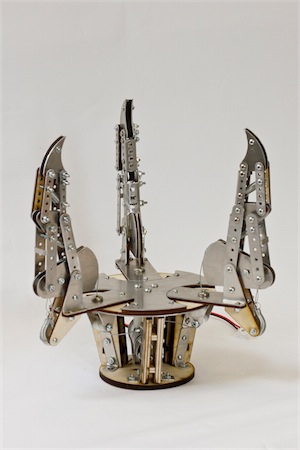
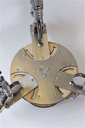
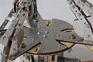
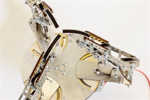
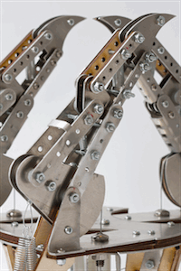
Three fingers, each extending about five inches above the main structure, spaced equally around the top platform of the cage. Each finger swings on a platform held by a setscrew through that platform, so the fingers can be reoriented for objects of different geometry — a sphere, a cylinder, a cube, a dumbbell.
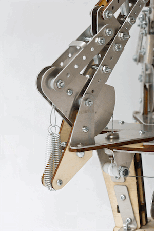
Each linkage component is 0.05in sheet metal, some with extra support layers of 1/8in birch plywood. We used fewer plywood supports per linkage to cut weight and stay competitive on the mass ratio. Every component carries a pattern of holes that double as adjustable spring mounts.
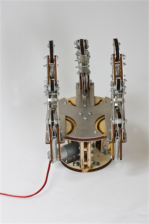
The cage is two circular discs mounted about 4in apart on wooden legs, joined with custom L-brackets cut to follow the slope of the legs. A sheet metal motor mount on the smaller platform constrains the motor, which drives a pulley with three cables attached. The cables run up the center of the cage to a triangular plate that redirects them outward to each finger.
Power and transmission
A cylindrical brushed DC gearmotor, 2.28″ × 0.98″ × 0.98″, with a 499:1 metal gearbox and a 4mm D-shaped output shaft. At 6V it turns at 12 RPM and can run continuously.
As the motor rotates it winds the pulley, raising or lowering tension in the cables. Each cable passes over a pulley beneath its finger, up through the top platform, and terminates at the finger base. Tension pulls the base down and the finger curls inward. Springs supply the restoring force, so reversing the motor slackens the cable and the fingers open again.
Fabrication
Sheet metal bending was straightforward. The motor mount needed a 120° bend to seat the motor properly, so we folded a paper pattern cut to 120° and used it to know when to stop — a surprisingly accurate way to get there. Every other bend was 90°.
The fingers were the most meticulous part. Washers between components reduced friction and stabilized the parts but were frustrating to place; tweezers, a little patience, and a steady hand did the job. We expected trouble drilling the cable holes through the bolts and hit none.
We had designed polymer grips for each fingertip, but the RP printer was down and the molds were never printed. That was our biggest setback, and in practice not a make-it-or-break-it one.
What we'd do differently
The hand has a beastly aesthetic and is, accordingly, heavy. It picks up the heaviest object, but it weighs more than it needs to, and there is room to cut mass while keeping the strength. We also regret not getting to the polymer molding — the grips would have made the hand far better at small and slippery objects, and we'd have learned polymer prototyping along the way.
Video
Rebuilt from the original ENGR2330 project page, which is still up at Olin but no longer renders its gallery.